Photogrammetry Workflow

Photogrammetry Workflow

It’s not feasible to model and texture every asset by hand especially when you can find those models in real life. So, in this project, I explored a workflow for creating high-quality assets using photogrammetry. The process begins by photographing an object, processing the images, generating the mesh, unwrapping it, fine-tuning the textures with lookdev, and optimizing it with LODs. Along the way, I learned the importance of good lighting, careful material handling, and rendering. In this post, I’ll share each step of the workflow. Although this is still a work in progress, it has a solid foundation to build upon.

Hardware

Slight blooming

To get started with photogrammetry, you do need some hardware. Although there are many examples using just a phone, that approach is limiting in terms of control, resolution, and cross-polarization, which I’ll get back to later.

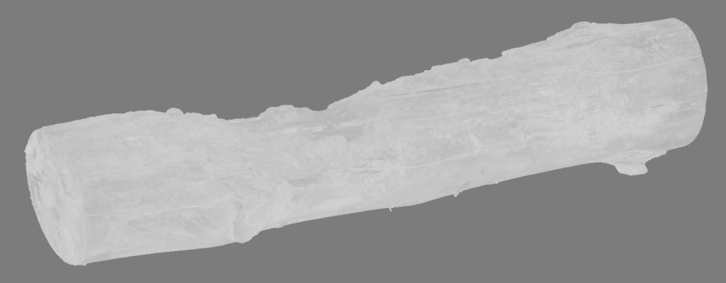
I already had a Sony A6000 camera. While it’s considered an older entry-level camera, it still offers enough resolution at 6024 × 4024 (24.24 MP). The lens is the weakest part of this setup, as it lacks overall sharpness and exhibits some chromatic aberration at shorter focal lengths. The pictures also show some blooming from the lens, which can unfortunately be visible in the resulting textures.

Cross Polarization

My photogrammetry rig

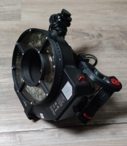
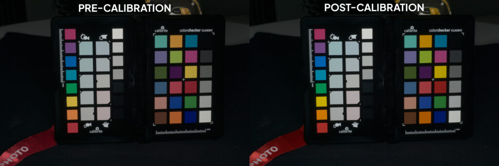
A key part of my capture setup was lighting. I used a Godox Witstro AR400 ring flash mounted around the camera lens, combined with polarizing filters on both the flash and the lens. This cross-polarization technique is a game-changer for photogrammetry: it dramatically reduces unwanted specular highlights and glare on shiny surfaces. The flash light is polarized in one direction, and the lens filter is aligned 90° off, so most of the reflected flash light (which stays polarized) is blocked. The effect is that the camera only “sees” the diffuse color of the surface, which is ideal for creating an albedo texture.

Choosing the Right Objects to Scan

Before taking photos, I had to decide what to scan. Not every object works equally well in photogrammetry. Generally, objects with rich surface detail, such as texture and color variation are the easiest to reconstruct. Smooth, reflective, or featureless objects are much harder. For example, a plain white wall or a shiny metal spoon will likely fail.

Hard-surface objects like cars or mechanical parts can also be tricky. They often combine smooth plastic or metal with sharp corners and seams. By contrast, organic or rough objects (stone, wood carvings, cloth) usually have plenty of random detail for the software to lock onto. I also avoided loose debris (broken bits or leaves), which can appear as floating junk in the model, a scanning nightmare. In short, good photogrammetry starts with good subject selection: textured, static objects on a clean, uncluttered base are ideal.

Post-processing Photos

With the hardware dialed in, I shot RAW images of each object, either in a dark, controlled room or outside (preferably in the shade, as the flash needs to be brighter than the sun to be effective). Shooting in RAW is important for full dynamic range and editing flexibility. I used Darktable, a great open-source software. The first step was basic exposure and white balance correction. Since I used a flash, the color was mostly consistent.

Critically, I used a ColorChecker target to calibrate colors. I always included a shot of the standardized color chart (e.g., X-Rite ColorChecker Passport) under the same lighting and environment as the object. Darktable’s Color Calibration module can read this chart and neutralize color casts. This step ensured that the same grey or skin tone patch on the ColorChecker came out exactly neutral in the photos, so all scans had consistent, true-to-life colors.

In practice, color-correcting was a big help. For example, if one day’s captures were slightly warm (yellow) and another’s were cooler, the correction flattened those differences. It also ensured that the textured models didn’t have weird color tints baked into the albedo.

Building the 3D Model in RealityCapture

Next came the 3D reconstruction. I loaded the edited photos into RealityCapture. It aligns the images by finding matching features and then computes a dense 3D point cloud and mesh. This process is mostly automated, just press “Align Images” and wait for it to finish.

However, there was a key challenge: capturing all sides of an object. To handle this, I did a two-pass scan. First, I placed the object upright and scanned it. Then, I flipped or tilted the object (e.g., put it on its side or upside-down) and scanned again. In RealityCapture, I imported the first photo set, aligned it, and created a preliminary model. Then I repeated this for the second set of photos.

This is where masks come in. You can use a reconstruction region to select which part of the model to keep, masking out the ground and background. This way, you can trick RealityCapture into thinking it’s a single object.

Then I aligned all the cameras again using both sets of images (with the masks applied). The result was a single, complete point cloud and mesh covering 360 degrees of the object. I then ran the Mesh Reconstruction on this combined region to generate a high-resolution mesh.

Unwrapping UVs and creating LODS

This high-poly (source) mesh has far too many polygons to work with, so I used the simplify tool to generate a lower-poly version. This mesh was exported to RizomUV, where I created the UVs. Then it was exported to Houdini for further processing.

The next step was optimizing for real-time or VFX use: creating levels of detail (LODs). This means having several versions of the mesh with progressively fewer polygons. I did this in SideFX Houdini using the SideFX Labs tools. In particular, the Labs LOD Create SOP (Geometry node) was extremely helpful. This node is essentially an all-in-one LOD generator: it can decimate geometry and clean it up while preserving the same UV layout. This means you can use the same textures for all the LODs (except for the normal map).

I also created a separate LOD with consistent mesh density. This is useful for shots made with offline renderers (such as Redshift) for close-ups, where you can subdivide the mesh as needed to add proper displacement.

Baking textures

With all the models complete, I started baking. Every model was imported back into RealityCapture. First, I calculated the albedo texture on the high-poly mesh. Since the UVs are consistent across all LODs, this only needs to be done once. However, normal maps must be baked for every LOD, as the topology changes. Using the same normal map across all LODs would result in artifacts.

Baked normal map

Cleaning Textures and Generating Utility Maps in Mari

With models and UVs ready, I moved to texturing in Mari. I imported the baked diffuse (albedo) textures and the mesh for cleanup and the creation of additional maps. Even with cross-polarized photos, real-world captures can leave artifacts: slight shadows, blurred regions, or crevices where the texture couldn’t bake properly.

albedo

I also needed the other PBR maps: Ambient Occlusion (AO), Metalness, and Roughness. Mari can bake AO using the high-poly mesh for fine detail.

AO (Ambient Occlusion)

For Metalness, most scanned objects in my tests were dielectric (non-metal), except for small screws or logos. I painted a simple black-and-white mask for the tiny metal bits. If the object were truly metallic, the whole surface would be white. This map is binary and straightforward.

Roughness was trickier. Photogrammetry can’t create roughness, so I estimated it from context by asking: “Is this surface rough or shiny?” In Mari, I typically converted the albedo to grayscale and tweaked the levels to produce a roughness map: lighter (near white) means rough/diffuse, and darker means smooth/specular. For example, paint or plastic might be about 50% gray, whereas polished metal bits are very dark.

Roughness

In summary, Mari lets you polish the albedo and create the missing maps. I ended up with a clean albedo texture (color), an AO mask, a metalness mask, and a roughness map. These four maps form a complete PBR material. I exported them as .png for each asset. Only the normal and displacement maps got additional .exr exports. This is because those maps benefit greatly from higher bit depth, resolving any stepping that can happen with 8-bit images. I used 16-bit for the normal map and 32-bit for displacement.

Consistent Look Development for Shading

At this point I had full 3D assets, geometry plus textures. But to ensure they appear correctly, I needed a consistent shading test. This is where look development (lookdev) comes in. A lookdev scene is a neutral, controlled lighting setup used to preview the object and its materials, ensuring the brightness, color, and surface response of each texture map is accurate and consistent.

A good lookdev scene should include the following key reference tools:

  • A grey ball: This represents 50% gray and is used to check both exposure and white balance.
  • A chrome ball: This acts like a mirror and shows the actual lighting environment being used.
  • A flat color chart: This helps detect if any tonemapping, gamma correction, or color shifting is being applied in the render.
  • A shaded color chart: Unlike the flat chart, this one is lit just like the subject, revealing how the lighting affects surface color.

I built a custom Houdini scene with these elements, plus a simple neutral backdrop and a standard lighting setup (an HDR environment, a soft key light, and a rim light). Each asset was loaded and rendered using a physically-based material that incorporated the pbr maps. The goal was to check that the albedo looked correct (no patches too bright or dark) and that the utility maps (roughness, metalness, AO) behaved as expected.

In practice, I kept all assets under the same lighting and camera conditions. For instance, I noticed that albedo textures from RealityCapture often appeared darker than expected. By comparing them to the grey ball and color charts in the lookdev scene, I could make exposure corrections as needed. This calibration step was crucial. Without it, assets might appear washed out or overly glossy under typical engine lighting. A consistent lookdev scene ensures your assets respond predictably and accurately across different lighting environments.

Challenges and Lessons Learned

Calibrating Albedo and Roughness Values: I often found the baked albedo maps didn’t have the “right” brightness. For instance, a white object might have looked slightly gray in the scan. This was mostly due to lighting/exposure during capture. My solution was the consistent lookdev scene mentioned above.

Capturing All Sides of an Object: As mentioned, scanning took two passes (regular and flipped) to cover all faces. We eventually split each scan into two sets of photos and used RealityCapture masks to merge them. In the end, the merged result was a fully complete mesh.

Overall, this hands-on experiment taught me that high-quality photogrammetry is a pipeline of many interlocking pieces. Good lighting (flash + cross-polarization) and photography are just the start. Equally important are the downstream steps: color calibration in Darktable, smart reconstruction with RealityCapture (masks and regions), clean UV unwrapping in RizomUV, and consistent lookdev shading.

Final assets

Closeups

Leave a Reply

Your email address will not be published. Required fields are marked *